Lightwave Communications

It is possible to transmit audio (and data, video etc) across medium to long distances by modulating light with either high power LED's or lasers. Equipment made by others has effective ranges well over 100 miles. The optical portion of the equipment I made is designed for shorter ranges. The electronics portion of the above transmitter will drive any optics.
For my optics I use a 3 watt red LED or 20mw red laser driven with a 20KHz pwm signal modulated by one of three sources: a front panel microphone, line-in (1/8"/3.5mm stereo jack) and an internal linux-based computer (raspberry pi zero version 2). The PWM modulator is a 12F683 PIC based microcontroller from microchip.com.
Here is a youtube video showing the system described here: https://youtu.be/ujk117eTPjM
The pic microcomputer has 8 pins, and is programmed in assembly. I feed in audio through an audio preamp (2N3904 transistor) which then goes to a op amp and a low pass filter at 4khz. From there it goes into an A/D converter on the pic chip and is sampled at 44.1khz at 10 bits. This audio modulates a pwm signal which drives either an LED or laser (or both simultaniously).
The resulting audio is comparable to an AM broadcast signal and actually sounds pretty good.
The led optical portion of the transmitter is shown below. It consists of a 3 watt LED mounted to a large piece of aluminum stock to dissapate the heat generated by the LED and dropping resistor. The laser (not shown) is mounted on the front of the enclosure. There is a bi-convex lens between the LED and the fresnel lens not shown.
(Click any image to view full size)


This is the interior of the electronics portion of the transmitter. The amplifiers and pic microprocessor are on the board to the left. The raspberry pi zero is to the right.

Above is an optical receiver. It is based on a design by K3PGP (k3pgp.org). It is partially shielded by copper plate to keep out some radio interference I had. It runs very well off of a 9 volt battery and provides low level audio that is fed to an old radio shack audio amplifier.
In the front is a credit-card sized fresnel lens. The resulting image is a small dot that is detected by a photo diode.
There is a lot of information at modulatedlight.org including construction projects for receiving and transmitting.
Low Level Audio Stages
Below is a schematic of the audio pre-amp, audio amplifier, low-pass filter and DC level shifter. Much of this is copied from my first version transmitter I made in 2013. I don't remember how much of this is original to me and how much is designed by others.

It's pretty basic. Either mic audio or line-level audio is first amplified by a 2N3904 common emitter amplifier which is a high impedance stage (light loading). This is fed to an NE5532, a low-noise op amplifier. The gain is controlled by the 10K panel mount pot. I found that if the pot is at 0 ohms, the stage oscillates. I put a 47 ohm resistor between the top of the pot and the 10uF cap to stop the oscillation.
Audio out of this stage is fed into a 4khz low pass filter. The output of this is shifted to 2.5 vdc with no signal. This sets the DC point to the A/D converter to mid-range. Audio drives this level to 5 vdc for the positive peaks and close to 0 vdc for the negitive peaks.
The 3 1K ohm resistors at the line level input keep my iPod from doing funny things when it's plugged in. The switch just after selects either the front panel mic or the line in. The line-in jack I use has two sets of inputs - one when there is no plug inserted and the jack lines themselves.
When there is no plug inserted, audio from the raspberry pi zero is fed to the jack lines thru a low pass filter so the raspberry pi zero can supply audio.
Light Transmitter - PWM Modulator
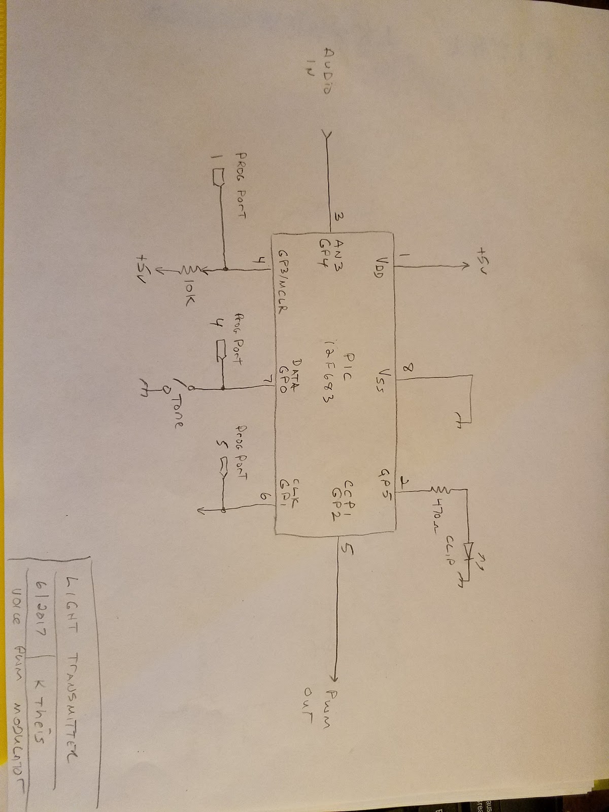
This is a schematic of the pic microcontroller. I use a 12F683 since it has a built-in clock, A/D converter and a PWM modulator.
Audio from the audio amplifier is fed into pin 3, AN3. Pin 1 is +5 vdc, pin 8 is ground. Pin 2, GP5, drives a res led which I use to show if the input signal is clipping. A tone switch is at pin 7, GP0. This disables regular audio and generates a set of tones that is used when initially aiming the transmitter/receiver set. The PWM output is at pin 5.
In addition, I use in circuit serial programming using pins 4, 6, 7, 1, 8. I use a pic-kit 3 usb programmer. Very useful.
LED and Laser Interface
Below is the schematic of the LED and laser inteface circuitry. I use an NTE295 to drive the LED, since it can handle the appx. 1A of current used by the LED.
The laser is driven by a 2N3904.

In the future I will use PWM from the pi zero to drive the LED/Laser which is the reason for the voice/data switch.
Raspberry Pi Zero Audio Out
Be default, there is no audio out of the pi zero. Using a couple of commands, the lines that are normally not assigned can be brought out to other pins, and these fed to a low pass filter. This provides a glitch free, acceptable audio output path.

I feed these 2 lines to the normally closed pins of the line-in jack. When a 1/8" plug is inserted, these lines are bypassed.
The sudo lines re-route the pwm lines to existing gpio lines. I place these two lines in /etc/rc.local which is run at system startup.
This is the front of the electronics of the transmitter:

The switch to the left selects line in/raspberry pi zero when up, the front panel microphone when down, and mutes the audio when in the center position.
To the right is the mic and a clip detect LED. This led flashes when the input signal is too strong.
To the right is the gain control.
The switches on the bottom select different functions of the transmitter. Voice connects the pwm modulator to the light source. Data lets the pi zero drive the light source.
The Tone switch (when up) disconnects audio and sends a tone sequenct to the light source. This is used when initially aligning the transmitter/receiver pair.
Main/Stby turns on the main output driver. For me, this is the LED. I could also connect a laser to this or a low power led for testing.
Laser/Stby turns on the driver for the laser.
Aim/Off puts full voltage on the laser. This is used to provide a bright spot using the laser for aiming. Useful when the high power LED is an invisible IR led.
The Mode button and the 6 lights above are connected to the raspberry pi zero.
When first powered up, the pi zero goes thru a sequence of initialization routines. When everything is done, the READY light turns on. This lets you know the pi zero is ready to be used. The pic pwm modulator is on immediately after power is applied.
The lights 1 thru 5 are selected by the mode switch, and represent different routines the pi zero can do to control the light source when the data switch is on.

This is the right side of the transmitter. These are ports used by the raspberry pi zero.

This is the back of the transmitter. The RCA jack is for the laser output. The Main Out red and black terminals connect to the hi power LED. The RF/DATA switch and the bnc jack are used to put the gpio data line to either the led/laser or the bnc jack. Used for testing.

This is the left side of the transmitter. The DC 12v jack is actually 12 v dc thru 30 v dc to power the transmitter. The line in jack is for external audio input.
Software
There are two programs I wrote to control the transmitter. The first is the assembly language program that controls the 12F683 pic microcontroller.
The source code is here: https://drive.google.com/open?id=0BxslhSudX_lgT1dXRnpVcDJsc2s
I'm making this GPL - you can use it, modify it, share it. If you modify it, let me know. Mayby I can use the changes you made.
This must be programmed into the pic microcontroller to make it work. If you are programming it, I assume you have the tools to also compile it. If not, get them (they're free) from the microchip.com web site.
The next is a Python program I wrote to control the raspberry pi zero. This runs when the pi zero is powered up. When shutting off the transmitter, the pi zero, having a file system, needs to be shut down in a controlled way. Pressing the mode switch when lights 1-5 are OFF will shut down the pi zero. After holding the mode button down for a couple of seconds, the ready light will begin to flash. When the ready light goes out, the shutdown sequence starts. A few seconds later the pi zero shuts itself off. This python program is mostly template code - it runs just fine the way it is, but you will see where you can add code of your own to make it more functional.
The source code is here: https://drive.google.com/open?id=0BxslhSudX_lgZWliODc4UTlrY1U
The pi zero has specific connections to the transmitter. The source code in the above link shows the gpio pins used. Just wire them thru 330 ohm resisters for the led's and to the switch for the mode switch.
I use a program called aplay on the pi zero. This plays a .wav file out of the 2 audio lines. aplay comes with the raspbian distribution. Once the audio jack is selected as the default audio output (run raspi-setup at startup and configure the jack as default) you can play audio with the following line:
aplay file.wav (where file.wav is the name of the audio file you want to play).
I'll add more code here as I write it.
Kurt 7/7/2017

Comments
Post a Comment